FKT DEVELOPMENT
To develop the fastest rim profiles, we need to understand how to apply real world conditions to a controlled test environment in the wind tunnel.
As part of our technical partnership with the Sports Engineering Department at Nottingham Trent University, we launched the #thinkwider project to analyse wind conditions at multiple points on the bike, specifically the front and rear wheels.
TYRE AND RIM WIDTH
The wider rim with becomes, the heavier it becomes. Also, a wider external rim width drives a wider internal rim measurement which makes it more challenging to remain ISO- and ETRTO-compliant.
Rim depth
Our #thinkwider design project showed the idea ratio of rim depth to rim width was > 4:1. For a gravel tyre width this would imply a total rim depth well in excess of our existing time trial and triathlon wheels.
Tyre tread
The tread pattern required for riding off-road has a far more significant and disruptive impact on aerodynamic performance than a road tyre.
Ride conditions
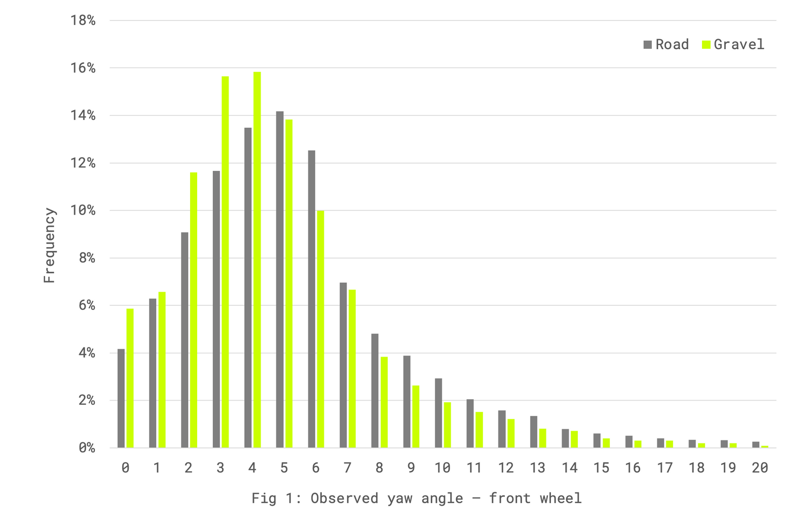
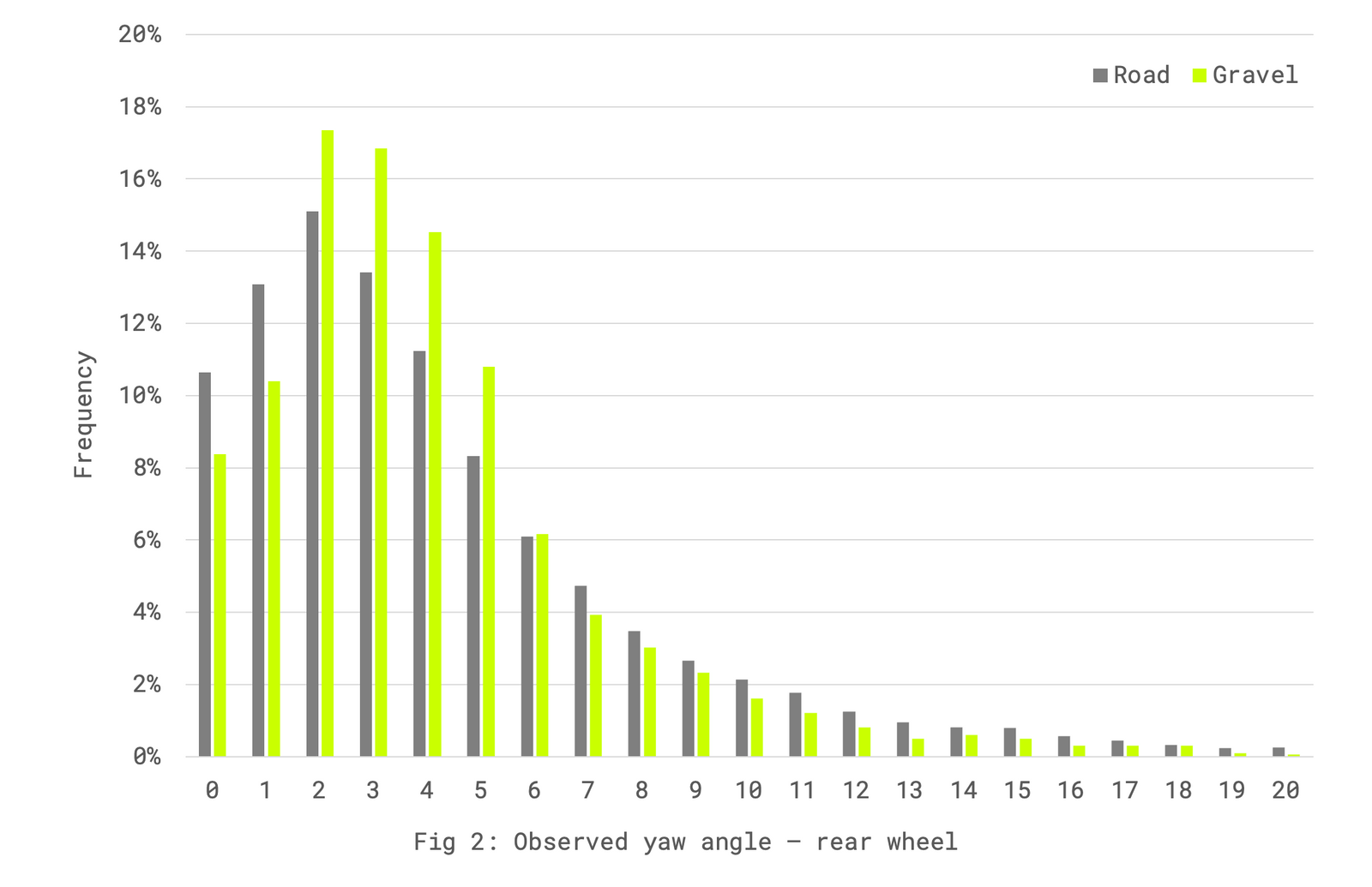
During the #thinkwider design project, our research showed that for road riding the yaw angle at the front wheel was on average 1.5 degrees higher than at the rear wheel. This led us to develop a differential front & rear rim profile to optimise for the differing yaw conditions.
For gravel riding, results showed that the yaw delta between front & rear wheels was far smaller at an average of c.0.4 degrees:
Design theory
In order to accommodate the expected design challenges, it was necessary to set out the main parameters for the project.
- External rim width capped at 40-45mm to allow for stated tyre clearance on current gravel frames.
- Internal rim width set at a maximum of 27.0mm to allow for ISO/ETRTO-compliance with a 35mm tyre.
- Rim depth constrained to a maximum of 50mm to maintain a suitably low rim weight and avoid handling issues.
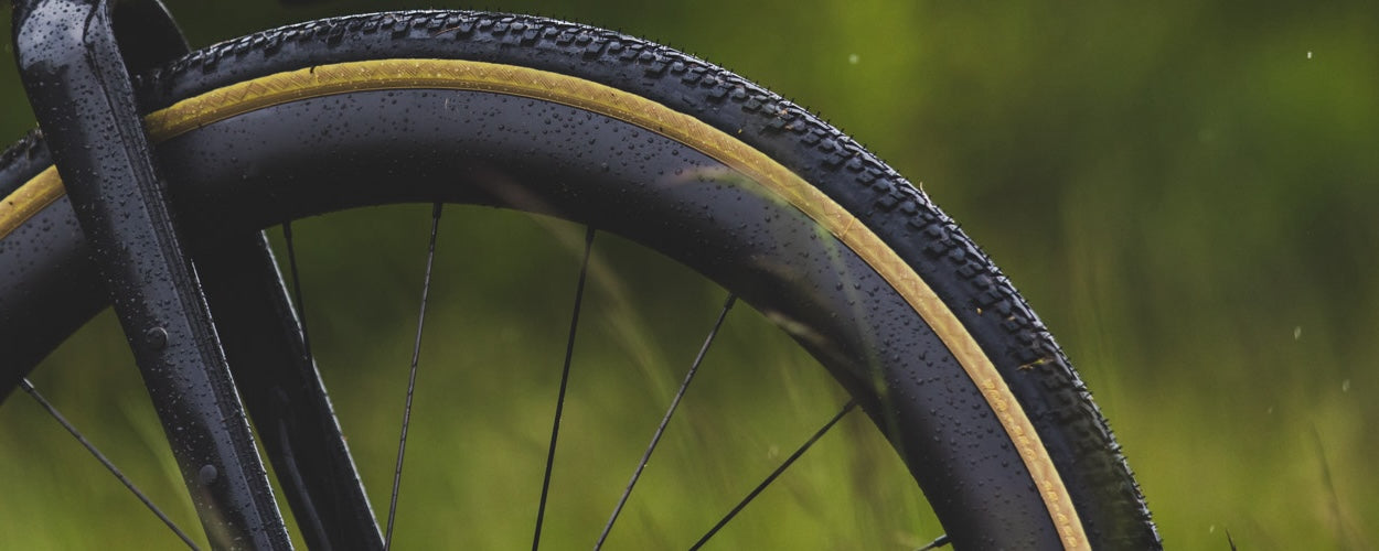
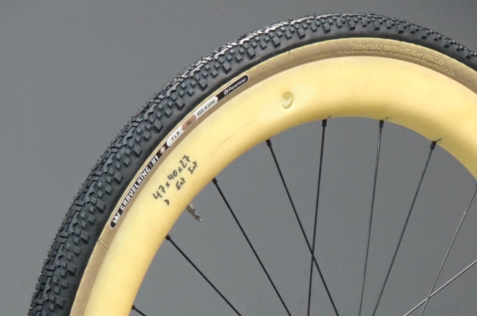
- Tyre tread based on Panaracer GravelKing X1 (40mm).
This was chosen as the benchmark tyre based on performance testing and its prevalence as tyre of choice in gravel racing.
The key development used in FKT was introducing a truncated foil (Kamm tail) design to the rim profile. Often used in automotive design, the Kamm tail has also been used by frame designers to comply with historic UCI 3:1 depth ratio regulations in frame tubing. The wake region behind the truncated foil mimics the effect of a teardrop as free stream flow does not enter this area. The reduction in boundary layer separation has a follow-on impact on reduced aerodynamic drag.
However, a wheel rotates so the a sharply truncated foil would not be suitable when the rim is the leading edge at the rear of the wheel. We therefore had to iterate a design using a hybrid Kamm profile, which presents a more curved surface as the leading edge.
CFD-DRIVEN DESIGN PROCESS
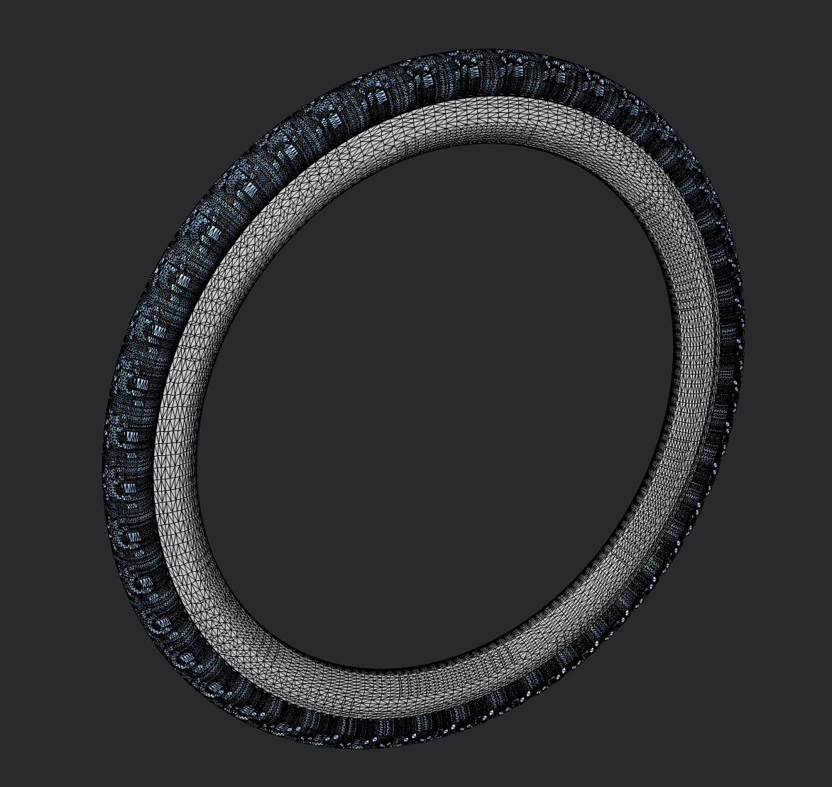
Given the importance of tyre and tread pattern, a set of initial prototypes (varying internal rim profile) were 3D printed and assembled into complete wheels.
A test tyre could then be mounted and 3D scanned back into the CAD software, offering a real-world representation of the tyre tread pattern and tyre casing profile.
This ensured that when moving on to the CFD testing stage of the process, the impact of the tyre on airflow could be more accurately modelled.
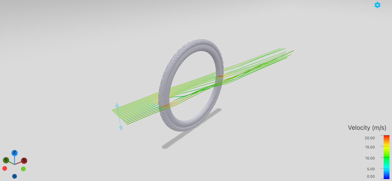
- A range of rim designs were tested in the CFD simulation environment, with outer widths ranging from 36 to 40mm and profiles based around a virtual foil depth of 120mm.
- Leading edge performance was tested with different levels of curvature at the base of the rim.
- Tests were conducted at 2.5 and 7.5 degrees of yaw, representing the lower and upper limits of the gravel-specific yaw window.
From this testing, a final design prototype was taken forward for physical production and benchmarking in the wind tunnel.

WIND TUNNEL TESTING
SEE RESULTS HERE